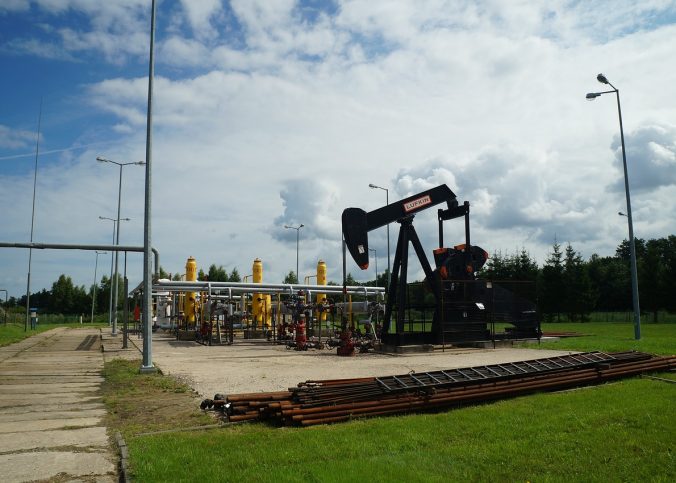
The oil and gas industry is one of the most lucrative industries in the world. There exist massive oil and natural gas reserves in Texas state. This sector has played a very great role in the development of the State. This is in spite of numerous calls by environmentalists to minimize the use of petroleum products due to their adverse environmental impact. Oil and gas is the primary natural resource and highest income generator of Texas State. The following are some of the ways through which this industry have contributed to the economic well-being of Texas:
Funding of the State’s Key Projects
This is the primary benefit of the industry to the State. The oil and gas industry has been responsible for the funding of significant projects such as schools, health sector, and other vital areas. Texas Oil and Gas Association reports that in 2015, the industry paid approximately $ 13.8 billion in taxes. The most prominent beneficiaries of this money are the State’s projects. These include projects like schools funding, and children insurance programs. The report showed that the oil and gas industry paid more taxes than even the major private companies in Texas.
The funds are paid to an Economic Stabilization Fund (ESF) commonly known as the “Rainy Day Fund.” This fund is in most cases used to help in covering budgetary shortfalls. This means that this industry primarily funds the general government provisions that you enjoy.
Jobs Creation
This sector employs approximately 400,000 people. The oil and gas industry also aids in indirect employment creation in related industries. The industry has enabled numerous companies that use oil and gas products to thrive. Your company is probably thriving due to the easy access to oil and gas in the state. In fact, Texas State is the leading State in the country regarding jobs creation.
The impact of this industry on the economy was felt during the Recession. During this period, the country’s unemployment increased by 10%. The recession was, however, least felt in Texas due to the presence of this industry. Unemployment was also high Texas, but it was significantly low as compared to other states. While other States in the U.S strained to recover from the Recession, Texas recovered all the jobs that were lost during this period.
Benefit to Private Citizens
Many private citizens across the Lone Star State have reaped the financial benefit of owning mineral rights. Since much of Texas is privately owned, oil and gas companies must purchase or lease mineral rights from landowners. Payouts from lump-sum sales and royalty payments can be extremely lucrative for these landowners, in Texas.
Essential Power Source
The natural source of power such as solar and wind cannot produce sufficient energy for an extended period. However, with oil, you are assured of power at all times of the year. The industry has helped the state to provide cheap energy to its residents. This means that the State’s funds that could have been used to purchase power are now used in other crucial projects.
Minimizes dependence of the Country on Others
Texas is the primary oil and gas producing state in the nation. Oil plays a very vital role in international politics. The industry has enabled the United States to remain a significant force in the world regarding energy provision. This industry, therefore, plays a very crucial role in the economy of Texas and the United States at large.